Differential Outputs

A Comparison of Oscillator Differential Transmission Outputs

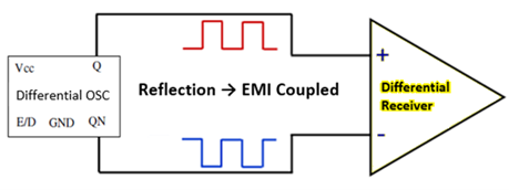
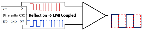
Differential transmission is a signal transmission technology that is different from the traditional single-ended signal transmission that uses a signal line and a ground line. Differential transmission carries signals on both wires. The two signals have the same amplitude, but opposite phases. The signals transmitted on these two lines are differential signals.
Differential Outputs Graph

LVPECL: Low-Voltage Positive Emitter-Coupled Logic

LVPECL is an optimized version of PECL that uses a 3.3V positive supply instead of 5V. PECL and LVPECL are differential signaling systems mainly used in high-speed and clock distribution circuits. A common misconception is that PECL devices are slightly different from ECL devices. In fact, every ECL device is also a PECL device.

LVDS: Low-Voltage Differential Signaling

LVDS is an electronic signal system that can meet today’s high-performance data transmission needs. When the system power supply voltage is reduced to 2V, LVDS is suitable for TFT LCD display devices with higher resolution than SVGA. It has been widely incorporated into a variety of devices and can be embedded in FPGA, ASIC or other components.

HCSL: High-Speed Current Steering Logic

HCSL is an interface standard for cable-based, short-distance serial high-speed data transmission. One of its most exclusive applications is the PCI Express (PCIe) physical driver. This is where the HCSL driver stage is integrated into the chipset to connect individual PCIe components, like a graphics card to host processor.

Differential Signaling vs. Single-Ended Circuit

Relative to a signal line and a ground line in a traditional Single-ended signal transmission, Differential Signals take a different approach.

The advantages are:

  1. Strong anti-interference ability. Phase noise is generally applied to both signal lines at the same time with a difference of 0. The phase noise has no effect on the logical meaning of the signal.

  2. Effectively suppresses electromagnetic interference (EMI). Since the two wires are close together and the signal amplitudes are equal, the amplitude of the coupled electromagnetic field between the two wires and the ground wire is also equal. The signal polarities are opposite and the electromagnetic fields will cancel each other out. Therefore, electromagnetic interference to the external environment is also minimized.
     
  3. Timing positioning is accurate. The receiving end of the differential signal is the point where the difference between the signal amplitudes on the two lines changes positively and negatively. This is used as the point where the logic 0/1 transition is judged. Ordinary single-ended signals use the threshold voltage as the transition point of the signal logic 0/1, which is greatly affected by the ratio of the threshold voltage to the signal amplitude voltage and is not suitable for low-amplitude signals.
Differential Outputs Graph

Compare Outputs

Compare the various output levels, schematic diagrams and typical applications.